Templates
System Analysis

About Functional Analysis / System Analysis
Functional analysis derives functions and subfunctions of a system and its elements. Functions are needed it in DFMEA to identify potential failure modes and are used during conceptual design to identify new solutions.

Identify functions of a system

Functional analysis returns a function tree.
Tree of design elements with functions and design options. Links to QFD 3. Can be used to populate a Morphological Table
The System Analysis component provides a tree diagram worksheet showing the system structure together with related functions and possible failures.
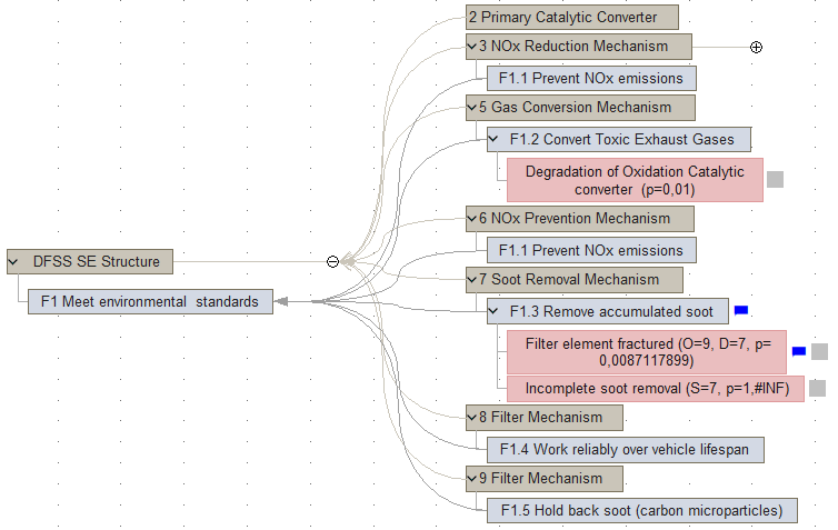
Use the insert buttons in the Home ribbon to create the system structure or to add a function to a system element or a possible failure to a function.
Drag lines from a sub-function to a parent function. You can also drag lines between possible failures in order to define the cause-failure-effect relation needed for FMEA and Fault Tree Analysis.
Worksheets
System Analysis and Concepts
The system analysis component can show both the generic setup of the system and one or more actual implementation approaches.
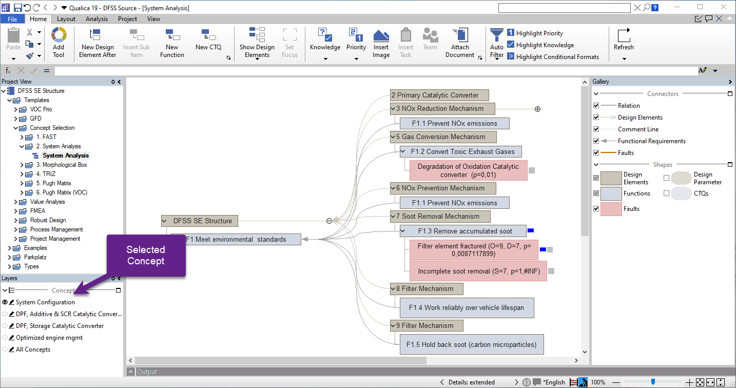
Use the layer control below the project browser to switch between the system configuration and the different implementation concepts.
At first, only system configuration will be available. Use the Morphological Box component to create new implementation concepts. For the generic system analysis (system configuration activated), use generic descriptions for the parts, e.g. motor instead of dc motor 25W.
- Changing the active concept will only show the actual parts used by the selected concepts and hide the generic descriptions.
Need more information? Open questions? Please let us know.